Overview
Features
Datasheet
Downloads
Supported Models
Image Gallery
tindie UPC 708088352553
Overview
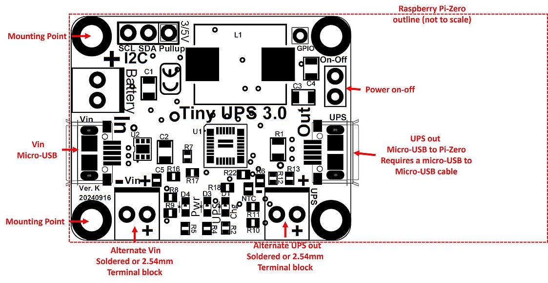
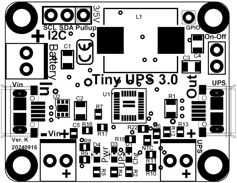
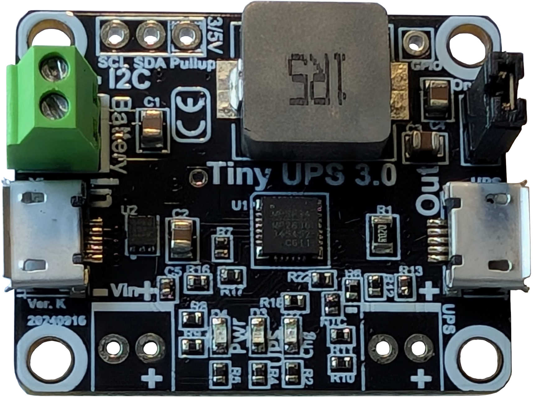
Tiny-UPS provides UPS for 5V USB or other power via an external Li-Polymer or Li-Ion battery (batteries are not included). Size and capacity of the battery does not matter to Tiny-UPS. The charge time and run time will change depending on the capacity of the battery. Tiny-UPS is an ideal power source for IoT devices and a Single Board Computer (SBC) such as Raspberry Pi, Arduino, ODriod™, Android devices and other USB devices. Mounting holes allow Tiny-UPS to be mounted on a Raspberry Pi-Zero as well as the Adafruit™ ADS1115 (or ADS1015) ADC boards.
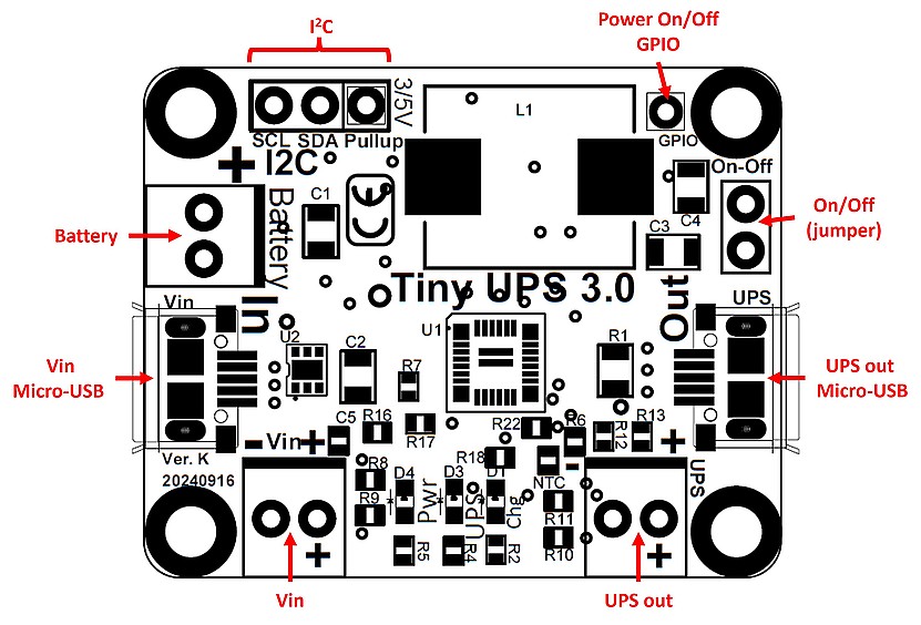
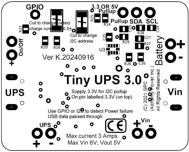
UPS functionality can be monitored using a built in ADC or by using the GPIO on Tiny UPS. A built in ADC gathers operating information and reports back the information via I2C. A separate pin allows for 3.3V (or 5V) pullup power for the I2C. Please make sure this pin is connected to a power pull up. Sample Python code monitors operating parameters and can shutdown unit when battery falls below a specified threshold.
GPIO indicates when power has failed. GPIO is high (3.3V) when power is on. GPIO is low (0V) when power has failed. The GPIO status can be used as a simple metric to time how long the UPS can operate before it needs to be shut down if your system does not have I2C capabilities. GPIO signals conform to 0V (low) and 3.3V (high).
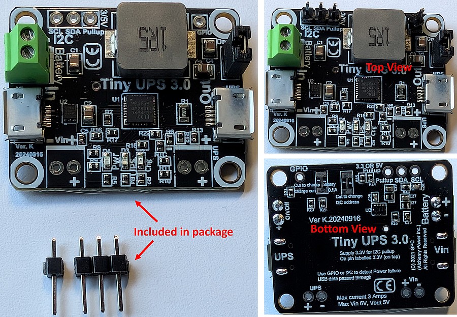
Tiny-UPS recommends a micro-USB power source capable of providing 5V, 3 Amps. Power on is indicated via the GPIO or by the Green LED. Battery charging by Yellow (Amber) LED. This LED goes off when battery is fully charged (at 4.2V). A blue LED indicates UPS operation when Input Power has failed.
When power is on, the output is powered and the battery is being charged, creating a parallel power path for battery charging and for Output Power. When Power fails, the battery V is boosted to 5V and the switch over is seamless.
Back to the Top
Features
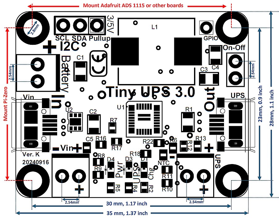
- Tiny size – 5cm x 2.8cm (1.38” x 1.1”)
- Use case: IoT devices, Arduino, Beagle, Raspberry-Pi, ODriod, others.
- Output: Micro-USB or solder, UPS 5V, 3A max via micro-USB.
- Input: Micro-USB or solder, 5V, 3A power adapter.
- UPS Battery: Li-Ion or Li-Polymer batteries.
- Charging: max 2A, CC-CV.
- Monitoring: GPIO for Power failure. I2C for monitoring Vin, Vout, Battery V, Temp. 3.3V pull up for I2C provided externally.
- LED’s: LED indicators for battery charging, UPS, Power.
- Safety: All electronics are turned off when battery V drops below 2.6V. Battery charges immediately when power is restored. Temperature controlled charging. Drained battery trickle charge. Over current protection.
- Low Drain: Charged battery remains charged for a long time.
- ESD/Surge: Input protected by TI Surge Protection Device. Protection for power surges and ESD.
Back to the Top
Pi Models Supported
 The PiZ-UpTime 2.0 product ships with the 2×4 pin connector soldered. Besides the Pi-Zero family of products, the connector on PiZ-UpTime 2.0 will also work with the Raspberry Pi (models A+, B+, Pi-2 and Pi-3, Pi-4, and other vendors adhering to the HAT pin and dimension standard). Some Pi-Zero products require you to solder the 40 pin header to the Pi-Zero, to leverage the full functionality (monitoring and shutdown via the Python script). If the header is not soldered, a micro-USB to micro-USB cable (not included) can be used to connect the PiZ-UpTime 2.0 to the Pi-Zero for UPS capability, however, the parameters cannot be monitored via the on-board ADC. The mounting holes for Pi-Zero match the two mounting holes on a Raspberry Pi (models A+, B+, Pi-2 and Pi-3, Pi-4). Using a PiZ-UpTime 2.0 on a Pi (models A+, B+, Pi-2 and Pi-3, Pi-4) only two standoffs can be used.
Older models of the Raspberry Pi with a 26 pin header are not supported